A hardware experiment by mhilo
A pen holder.
One iteration
at a time.
Putting Copic pens in a Graphtec plotter sounds simple. Getting the fit, grip, and writing height right is where the interesting part begins.
In development / Updated
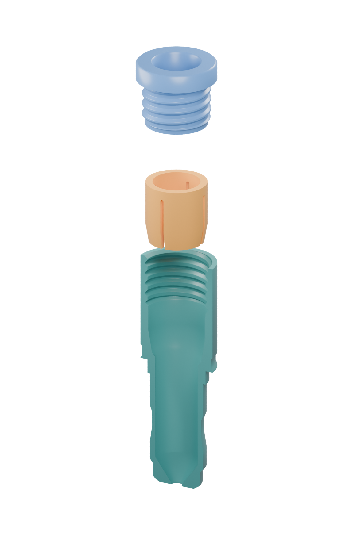 01 Screw cap
02 Slotted insert
03 Holder body
01 Screw cap
02 Slotted insert
03 Holder body
The complete holder is still in development.
Small tolerances.
Real ink.
A 3D-printed adapter for using Copic Multiliner pens in a Graphtec plotter.
The aim is a holder that seats in the carriage, keeps the pen steady, and puts the writing point at the right height. It started with a snug-fitting body. New pen measurements and carriage tests have turned it into a series of small, focused prototypes.
Two paths are being explored: refining the holder’s shape, and developing a screw-adjusted grip that can hold the pen independently of a tight bore.
Fit the carriage
Seat the flange and reach the clamp without catching on the metal throat.
Hold the pen
Accommodate different pen shapes while keeping the barrel from sliding.
Set the height
Establish a repeatable writing-point position before a complete plotting test.
Each print asks
a smaller question.
From a complete body to isolated fit samples. The version numbers follow the original design files.
V09–10Start with a working printThe solid-holder baseline
V9 provided a successful print. V10 adapted that profile for the measured 1.0 pen shaft, widening the outlet to 2.65 mm while retaining the 10.05 mm barrel bore.
Lesson: A successful earlier print establishes a starting point; each new pen still needs its own fit check.
V11–12Let the holder seatClear the carriage, then check the clamp
V11 removed a protruding ring and shortened the holder by 7.12 mm, using the measured pen projection to target a 33.12 mm flange-to-writing-point distance. V12 reduced the mounting cylinder to 13.30 mm.
Result: The narrower body passed through the carriage, but the clamp did not grip beneath the flange.
V13–14Find the contact zoneA collar, with a hard depth limit
V13 added a local 14.50 mm collar to reach the clamp. A new measurement showed that the enlarged section could extend only 3.20 mm below the flange before hitting the metal throat. V14 shortened the collar to that limit.
Lesson: Passing through the opening and being held by the clamp are separate tests. A short clamp sample makes those checks cheaper.
V15Make room for another penIsolate the barrel fit
A second barrel measured 9.85 mm, compared with the earlier 9.75 mm. An 8 mm-long gauge increased the bore to 10.15 mm to test clearance without printing a whole holder.
Status: A fit gauge was exported. A complete universal holder was not established.
V16Measure a working referenceRevisit the carriage profile
Measurements from a working PHP-31 holder informed a new carriage sample: an 11.93 mm neck, 13.96 mm main body, and 10.90 mm lower section. A print-friendly ramp adapts one of the shoulders.
Status: The sample passed mesh and slicing checks. Physical seating and clamp grip are still awaiting confirmation.
V17Test the shared nose shapeLatest holder iteration
Measured shoulder positions from three pens informed a shared nose recess. The 15.50 mm sample tests pen entry and nose clearance independently of the carriage mount.
Print feedback: All three pens fit into the sample’s opening. Shaft emergence, individual tip projection, and retention still need confirmation.
See the current test statusPath B / Adjustable grip
A different way
to hold on.
A screw cap pushes a slotted insert into a tapered seat. The idea is to close the insert around the barrel, giving the pen an adjustable grip.
Concept 01’s three parts printed and reportedly fit together. Tightening the cap, however, did not appreciably increase grip: the pen still slides.
Explore the original mechanism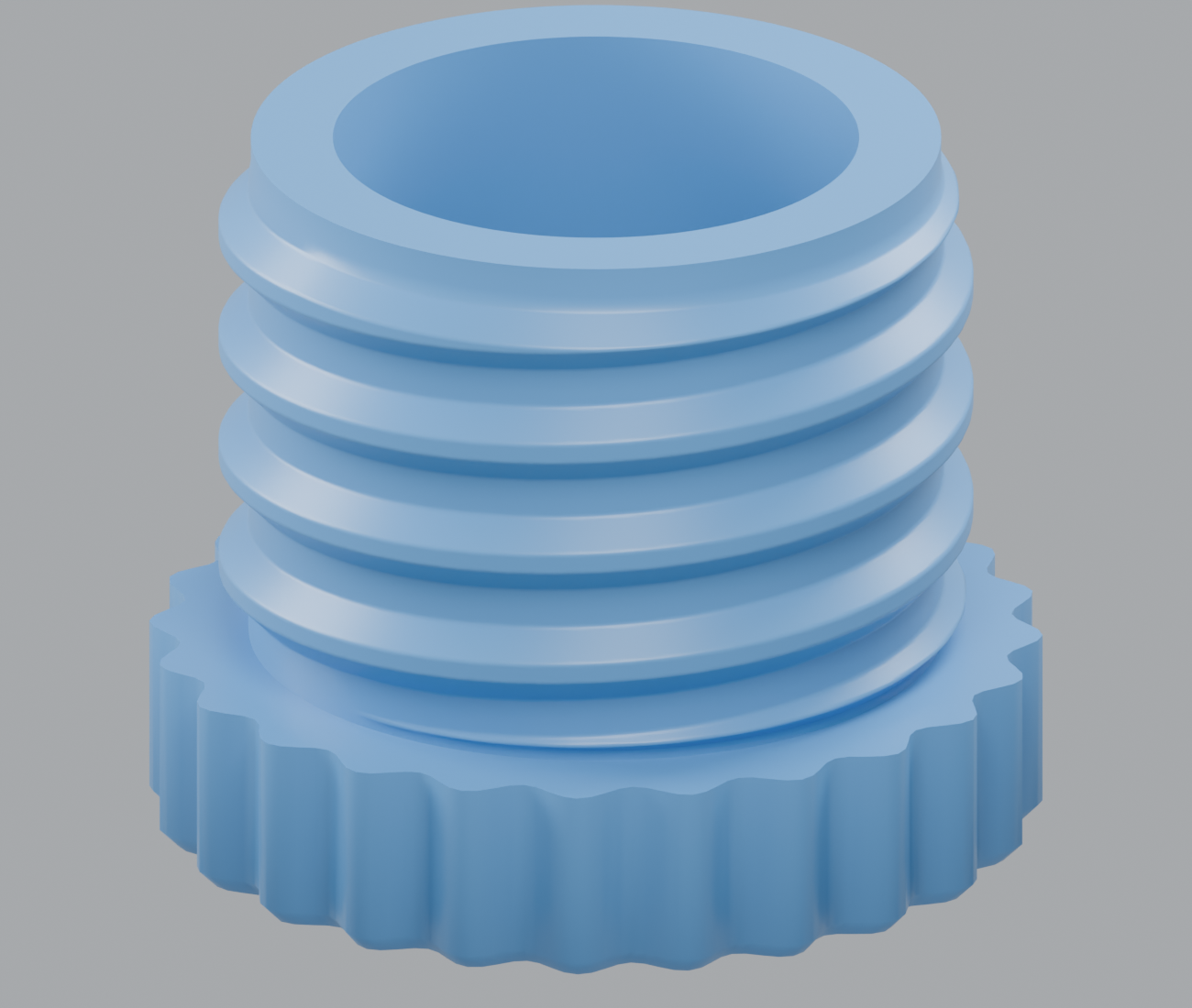
More grip for your fingers.
V2 adds 24 rounded ridges to the cap. Its thread, bore, and pressing face stay the same. This addresses the slippery cap; it does not yet resolve the sliding pen.
Sliced successfully. Physical print and grip test pending.
Progress you
can put a finger on.
The project is in physical testing. There is no validated, complete universal holder yet.
Observed in print tests
The pieces
are taking shape.
- A successful V9 print established the early baseline.
- All three pens enter the V17 sample’s opening: 1.0, 0.5, and 0.005, using the recorded pen labels.
- The three Concept 01 grip parts printed and reportedly fit together.
Still being resolved
Holding steady
is the next hurdle.
- The pen still slides in the tightened Concept 01 grip.
- V16 carriage seating and clamp grip are not yet confirmed.
- V17 shaft emergence, writing-tip projection, and retention remain unconfirmed.
- The ridged V2 cap has not yet been printed or tested.
Mesh and slicing checks describe the digital model and toolpaths. Physical grip, repeatable writing height, and full plotting performance require their own tests.
Explore the prototypes.
These are test parts for specific questions. The V16 and V17 samples are not complete plotting holders.
Read the current test notes before printing. Parts are supplied in millimeters and in their intended print orientations.
Original illustrated review